
SERVICE 01 / 04 — 32.9346° N, 97.2517° W
Integrated Engineering Services
Engineering, geospatial technology, and digital solutions combined to carry telecom, utility, and infrastructure projects from structural feasibility through construction-ready design to regulatory approval.
TRUSTED BY
INDUSTRY LEADERS






THE PROBLEM
Design, permitting, and modelling — usually handed between disconnected vendors.
Spatial Alphabet operates this pipeline end to end, on one team and one dataset: pole loading analysis establishes structural feasibility, fiber and power line design turn that feasibility into a construction-ready package, and permitting clears the regulatory path to construction — with BIM and CAD digitization carrying the same rigor into modelling and drafting.
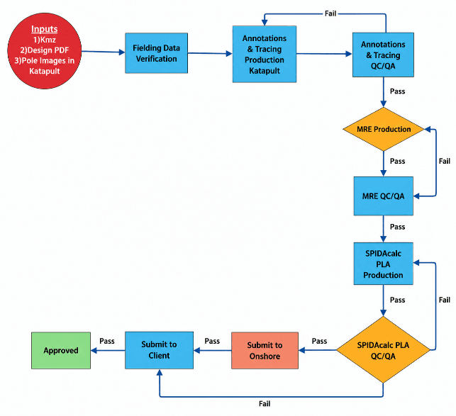
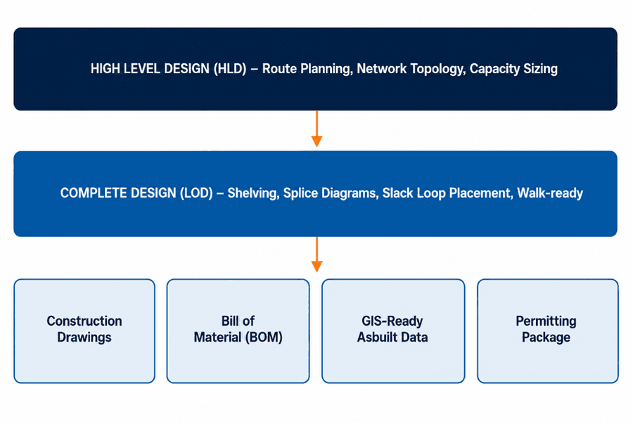
FIG. 01 — INTEGRATED ENGINEERING SERVICES WORK PRODUCT
WHAT WE DELIVER
3 capability areas.
Telecom Engineering
Pole Loading Analysis, Fiber Network Design (HLD/LLD), and Permitting.
Pole Loading Analysis (PLA)
Structural pass/fail analysis for telecom attaches, electric utilities, and municipalities under NESC, GO95, or ASCE loading — from GPS/Katapult field capture through PLS-CADD/PLS-POLE, IKE, SPIDAcalc, and O-Calc Pro modelling to a certified report with make-ready cost estimation.
Fiber Network Design (HLD/LLD)
High-Level Design sets route, topology, hub siting, and fiber-count sizing; Low-Level Design delivers pole-by-pole staking, splice diagrams, slack-loop placement, and a full bill of materials — one authoritative construction-ready package.
Permitting
The full approvals sequence — pole-attachment and right-of-way applications, make-ready coordination with pole owners, and tracking every application through to Notice to Proceed (NTP).
Power Line Systems
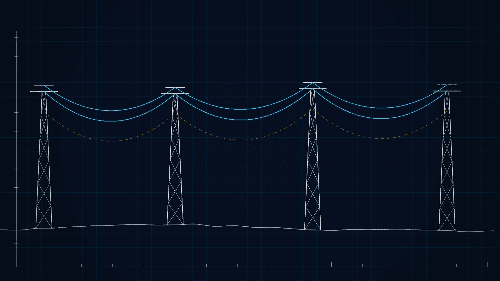
Transmission and distribution engineering on PLS-CADD and PLS-POLE, plus AutoCAD network design.
Transmission & Distribution Line Engineering (PLS-CADD & PLS-POLE)
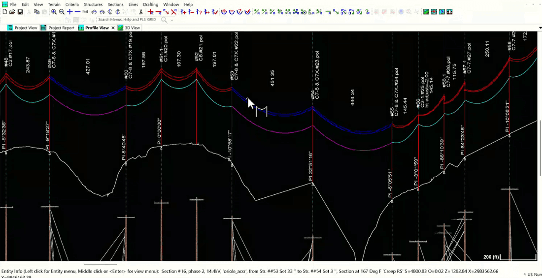
Terrain modelling, alignment optimization, structure spotting, and conductor sag/tension/clearance analysis under wind, temperature, and ice — with structural modelling of poles, cross-arms, insulators, foundations, and guys against ANSI O5.1 and ASCE.
Electrical Utility Network Design (AutoCAD)
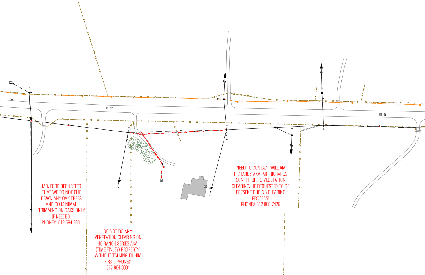
GPS field survey data converted into engineering-ready AutoCAD drawings — poles, overhead and underground lines, transformers, anchors, and junction boxes — as Exhibit Drawings for approvals and Construction Drawings for field crews.
Engineering Design Drawings for Overhead Construction
Standardized construction packages — pole hole details, anchor locations, offsets, clearances, framing, and cross-sections — drafted to approved utility standards and QC-reviewed before release.
BIM
Data-rich 3D models integrating graphical, engineering, and asset information across the project lifecycle.
Scan to BIM
Point-cloud and laser-scan survey data converted into structured, information-rich Autodesk Revit models for 3D modelling, infrastructure visualization, and multi-discipline coordination.
Scan to CAD
Scanned survey data translated into accurate 2D/3D CAD drawings, carrying the same accuracy standards applied across every Spatial Alphabet CAD deliverable.
Paper to CAD
Legacy paper drawings and records digitized into clean, editable CAD — preserving original design intent while making historical infrastructure records usable in modern workflows.
TOOLS & PLATFORMS
- PLS-CADD
- PLS-POLE
- SPIDACALC
- O-CALC PRO
- AUTOCAD
- KATAPULT PRO
- AUTODESK REVIT
HOW AN ENGAGEMENT RUNS
Four steps. QC gates at every one.
01 — STANDARDS INTAKE
We absorb your design standards, assembly units, and QC criteria before the first structure is modeled.
02 — PILOT CIRCUIT
One feeder, line section, or fiber route delivered end-to-end against your acceptance checklist.
03 — SCALED DELIVERY
Hyderabad execution with US engineering oversight — throughput that flexes with your program.
04 — APPROVAL & HANDOFF
Deliverables arrive construction-ready, with QC evidence attached. Zero rework is the spec.
WHERE THIS SERVICE LANDS
Related industries
PILOT PROGRAM
Scope a pilot for integrated engineering services.
Scope a Pilot →Paid or pro bono — your call. We take a real slice of your program, deliver it to production standard, and you evaluate the result before committing anything further.
01 — SCOPE
We define a bounded, representative work package with you — real data, real specs, one to three weeks.
02 — DELIVER
Our dual-shore team executes under the same QC protocol as a full engagement. No demo-grade shortcuts.
03 — EVALUATE
You audit the deliverables against your own acceptance criteria. Then decide — with evidence, not promises.